Copyright ![]() 2001 - Rod
Elliott (ESP)
2001 - Rod
Elliott (ESP)
Page
Updated 05 Nov 2001
Rod Elliott (ESP) - Passive Crossover Network Design
Copyright ![]() 2001 - Rod
Elliott (ESP)
2001 - Rod
Elliott (ESP)
Page
Updated 05 Nov 2001
Highly recommended reading is Project 82 - Loudspeaker Test Box. This will make quite a bit of the testing described below redundant, and you will be able to see at a glance what network is best suited to your drivers. It does not do notch filters though, so this is something that you may still need to determine mathematically (or just cheat and use the spreadsheet :-)
Most people who have read my pages will know by now that I am not a fan of passive crossovers. However, sometimes it is the only sensible approach, or is necessary because of financial considerations or just for simplicity. Before deciding on the use of a passive rather than active crossover, the following article will surprise you - perhaps even enough to make you decide to go active after all.
Where passives are to be used, I prefer a simple 6dB/octave unit, but in many cases this is not possible - most commonly because of the low rate of roll-off, which can cause excessive power to be delivered within the stop band. This can excite the resonant frequency of tweeters, and causes a honkiness in the upper midrange - usually subtle, but audible nonetheless.
A conventional Butterworth 12dB/octave filter is still by far the most common crossover, but is now under threat from the Linkwitz-Riley alignment. The latter has a crossover frequency where the output of each filter is 6dB down, and this has the advantage of a zero rise in output at the crossover frequency. The "conventional" crossover filter is 3dB down at crossover, and the summed output shows a slight peak of 3dB at the crossover frequency. This phenomenon occurs with both electronic and passive crossovers using the Butterworth alignment.
All crossover networks have problems. Some have more than others. The ideal loudspeaker is a single point source (i.e. small compared to all wavelengths of interest) that reproduces all frequencies. Such a driver is not possible with any technology currently available, so (as always) we must compromise.
The most common compromise is to use two (or more) loudspeakers, each optimised for the frequency band it must cover. Since it is highly undesirable that drivers intended for high frequencies be subjected to low frequencies (and vice versa), the audio signal is separated into "bands" by a crossover network - either electronic or passive, or a combination of the two.
In this article, I have concentrated on a two-way crossover network. Three-way (and above) will become a nightmare if you must use passive crossovers all the way through. My recommendation is that all low frequency crossovers should be active, and if you must use a passive network, then it should be for the mid to high frequency section only. The basic principles apply to all drivers regardless of frequency range, so it is not hard to extrapolate the examples given to low frequency networks.
The purpose of this article is to explain how to obtain the best possible performance from a passive crossover network, and avoid the major pitfalls that await us in our endeavours. Crossovers are not simple. Electronic units require us to have a multiplicity of amplifiers (one for each loudspeaker driver), and passive units impose other constraints and limitations - not all of which are satisfactorily addressed by loudspeaker manufacturers (including some "high end" components).
There is information presented here that I have not seen in any other material on the subject of crossovers, with the exception of my article, "Biamping - Not Quite Magic, but Close". Specifically, this is to do with the shift of filter frequency and alignment that occurs when a voice coil is hot. Since a stable operating temperature will never be achieved with music signals, there will be a constantly shifting crossover frequency, and a peak in the frequency response where the amplitude is dependent on the power at any instant in time. This cannot be considered a satisfactory situation, and is quite possibly one of the most compelling reasons to use active crossovers whenever possible.
The article that follows requires that you are very familiar with the use of a spreadsheet or scientific calculator. There are many calculations and measurements to be made to get it right - but the end result will be well worth the effort.
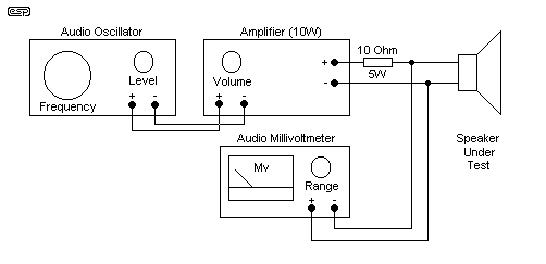
Figure 1.1 - Speaker Test
Setup
You will need to set up the equipment shown in Figure 1.1 to carry out any tests on the speakers. The millivoltmeter may be a digital, if you are sure that it has a good enough frequency response. A frequency meter is also very helpful, but is not essential if the oscillator is well calibrated. If an amp larger than 10W is used, make sure that you keep the volume right down - most tests will require a maximum of 1V RMS, so even a 1W amp will be enough.
A spreadsheet is now available to perform the maths for you. You still need to measure the drivers, but once measured, you can simply insert the values into the spreadsheet for a complete starting point. The spreadsheet cannot compensate for all possibilities, and some experimentation will almost always be needed to arrive at the optimum solution.
Passive Crossover Design SpreadsheetIdeally, when you use the spreadsheet, you should use the actual measured impedance of the loudspeakers, rather than the quoted "nominal" impedance. Using the test set shown above makes this quite easy.
| Vr = Vin - Vs | Vr is voltage across resistor, Vin is unloaded voltage, Vs is voltage across speaker |
| I = Vr / R | Where I is current, and R is the value of the resistor (10 ohms is suggested) |
| Z = Vs / I |
Assume an input of 1V, R = 10 ohms and Vs = 400
mV
| Vr = Vin - Vs | = 1 - 0.4 = 0.6 V |
| I = Vr / R | = 0.6 / 10 = 0.06 A |
| Z = Vs / I | = 0.4 / 0.06 = 6.67 Ohms |
This calculation is also done by the spreadsheet.
A comparison of filter alignments is in order, so that the reader not
experienced in such matters will know what I am on about. There are three
primary filter alignments that can be used, and they differ only in the damping
(or "Q") factor. Q, or "quality factor" is an abstract term that is
applied to many passive components in many applications, and is effectively the
inverse of damping. Thus, Q=1/d or d=1/Q. Fascinating stuff (if you
happen to be a mathematician :-)
| Filter | Main Characteristic | Other Characteristics | Q |
| Butterworth | Maximally flat amplitude | - | 0.707 |
| Bessel | Maximally flat phase | Fastest settling time | 0.5 to 0.7 (typ) |
| Chebychev * | Fastest rolloff | Slight peaks / dips | 0.8 to 1.2 (typ) |
One of the "magical" number in electronics is ![]() 2, or 1.414, and
its inverse, 0.707 and the latter can be seen in the table as the figure that
provides "maximally flat" frequency response. This means that the response
in the pass band is as flat as it can possibly be, until the cutoff (-3dB)
frequency is reached. This forms the classic Butterworth filter that has
been the mainstay of nearly all crossover systems in common use.
2, or 1.414, and
its inverse, 0.707 and the latter can be seen in the table as the figure that
provides "maximally flat" frequency response. This means that the response
in the pass band is as flat as it can possibly be, until the cutoff (-3dB)
frequency is reached. This forms the classic Butterworth filter that has
been the mainstay of nearly all crossover systems in common use.
A Bessel filter has a slower and "sloppier" response, that starts to droop well before the cutoff frequency, but has the minimum phase shift, and one that is comparatively gentle. All 6dB filters are Bessel, and have a Q of 0.5 - this cannot be changed by any topology, regardless of whether electronic of passive crossovers are used.
The Chebychev filter has a slight rise in amplitude just before the cutoff frequency, the magnitude of which is determined by the Q. The higher the Q, the greater the peak in the response. Higher order Chebychev filters will have dips as well as peaks. Many vented subwoofers use a Chebychev response for the port tuning, as do quite a few sealed enclosures. The Q will typically be about 0.8, so the rise in amplitude is less than 1dB, but some will use a Q as high as 1.0 to make the loudspeaker sound as if it has more bass.
Chebychev filters are rarely used in crossovers - some electronic crossovers have used them, but these are most uncommon. This alignment will not be discussed further (except where it happens by accident due to impedance variations).
The amplitude and phase of a filter is easily plotted by means of circuit simulation. Amplitude response may be measured using a simple signal generator, small power amplifier (for loudspeaker crossover filters) and an AC voltmeter, which must have a bandwidth that covers the audio spectrum - not all do, especially cheap analogue and digital meters. Phase shift is very difficult to measure without an oscilloscope. Digital oscilloscopes have the added advantage of cursors that can be used to obtain accurate readings of time delay at any given frequency, and phase shift can be calculated from this.
Fortunately, once armed with enough information, phase shift measurements are not generally needed. This simplifies the design process considerably, since the phase shift of any given filter type will be known in advance.
In this section, we shall examine some of the possible influences that have (or may have) an adverse effect on the performance of a crossover network. Some of these are well known and are catered for in many (but by no means all) commercial and hobbyist (DIY) loudspeakers. Others are less well known, and are ignored completely by virtually all loudspeaker builders - perhaps with good reason, perhaps not.
3.1 Speaker
Impedance
One area where measurement is essential when designing
passive crossovers, is the loudspeaker driver itself. There is usually
very little information in the makers' data that will prepare you for the
behaviour of a loudspeaker / crossover network combination, and these data are
usually derived empirically. In some cases the voice coil inductance will
be quoted, and if so, this may be a bonus, as will be shown shortly.
3.1.1
Woofers and Midrange Drivers
In almost every case, the crossover
frequency selected for the woofer and midrange driver will be at a frequency
where the voice coil inductance is significant. As frequency increases,
the effect of the voice coil inductance is to increase the driver's impedance,
and this plays havoc with the crossover network's performance.
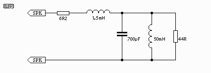
Figure 3.1 - Equivalent Circuit
of a Loudspeaker
Examination of a simulated low frequency driver depicted in Figure 1, shows a large peak at resonance, and a relatively small section where the impedance is flat. This equates to the nominal impedance of the speaker, but as shown below, this covers a limited frequency range. The biggest problem for the crossover is not resonance (for a woofer, at least), but the rise in impedance as the voice coil inductive reactance starts to become significant relative to the nominal impedance.
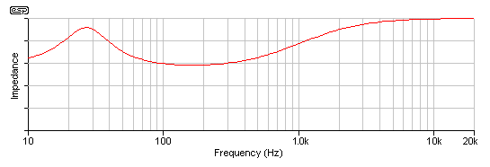
Figure 3.2 - Impedance Curve of
"Simulated" Loudspeaker
This is most commonly corrected with a zobel network (Figure 3), connected in parallel with the speaker. As the inductive reactance rises, the capacitive reactance falls, and the resistance is typically made equal to the DC resistance of the voice coil. The net result is a flat impedance curve, as shown in Figure 3.4. This is absolutely essential for proper behaviour of the crossover network, but sadly is not used in a great many designs. The result is a shift in the crossover frequency, and phase response that is not exactly ideal. The crossover may be designed to work with the impedance actually presented by the driver, in which case it will be asymmetrical, having different inductance and capacitance from the theoretical values that one might expect.
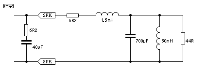
Figure 3.3 - Addition of an
Impedance Correction Zobel Network
The zobel network will flatten the impedance of the speaker, but at the cost of power dissipation, and a slightly lower than expected overall impedance. Naturally, the power dissipated by the resistor is turned into heat, not sound, reducing effective efficiency. The lower impedance may cause some stress to certain amplifiers, but most should be able to cope with the slight extra loading. It must be understood from the outset that the flattened impedance curve does not make the speaker perform any better at the higher frequencies - the sole purpose of the zobel network is to ensure that the impedance presented to the crossover network remains essentially constant over the frequency range where variations would cause an unacceptable frequency response variation in the filter network. The determination of the required values for the zobel network is most easily done by measurement and experimentation.
If the voice coil inductance is known, then a suitable value of capacitance may be calculated quite readily. The first thing to determine is that frequency where the inductive reactance is equal to the DC resistance of the voice coil ...
f = Rvc / 2Where ...Lvc
f = frequencyOnce this figure is found, it is a simple matter to calculate the capacitance for the zobel network ...
Rvc = Resistance of voice coil
Lvc = Inductance of voice coil
C = 1 / 2Using the simulated speaker above as an example, we already know that Rvc is 6.2 ohms, so ...f Rvc
f = 6.2 / 2 *It should come as no surprise that this is almost exactly the value found by simulation, so we can safely assume that the formula works, and is easy enough to use. The resistance will nearly always be approximately equal to the voice coil resistance - in some cases it may be found that a small variation is needed, but this is unlikely to be significant.* 1.5-3 = 658Hz
C = 1 / 2 ** 658 * 6.2 = 39-6F = 39uF
Although the capacitor does not have to be "audiophile" quality, and a bipolar electrolytic could be used, the main problem with bipolars is that they are not stable over time. I recommend that polyester, polypropylene or oil filled paper cap be used, and suggest that you will be faced with a not inconsiderable expense to implement this scheme properly. Is it worth it? Absolutely!
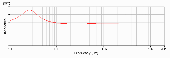
Figure 3.4 - Resulting
Loudspeaker / Zobel Impedance Curve
Naturally, it is important that the crossover is designed for the actual (rather than the nominal) impedance presented by the driver at the crossover frequency. An 8 ohm speaker will rarely be 8 ohms in reality, and this is especially true when an impedance correction circuit is used.
As noted above, one could also design the crossover for the impedance actually presented at the crossover frequency, but this varies with frequency. Unless the impedance remains reasonably constant for at least 2.5 octaves (and preferably more) above and below the crossover frequency, the network cannot be expected to provide a predictable response. As a direct result of this, a 6dB/octave passive crossover at (say) 300Hz is barely acceptable, because of the impedance peak of the woofer. Although it is possible to equalise the woofer's impedance peak, the components needed will be very large (electrically and physically), and will be very expensive.
If the loudspeaker is installed in a vented enclosure, then there will be two impedance peaks to equalise out - this can become very tedious, and will be costly to implement. There is usually little to be gained by equalising the woofer impedance peaks, and if an electronic crossover network is used, there is absolutely no reason to do so.
When you have completed the network, connect it (and the speaker) to the test setup shown in Figure 1.1 and measure the response. It should be quite flat (within 1dB) up to the highest frequency of interest.
3.1.2
Midrange and Tweeter Drivers
Most tweeters and midrange drivers
can benefit from using a compensation circuit at their resonant frequency when a
passive crossover is used. This is especially true if you are using
a crossover network with a slow rolloff, or the frequency is too close to the
resonant frequency of the driver. With a 6dB/octave filter, I suggest an
absolute minimum of about 2.5 octaves between the driver resonance and crossover
frequency. A tweeter with a 900Hz resonance should therefore be crossed
over at a minimum of 2,500Hz, but preferably higher. If you use the
minimum possible frequency separation, there will be a small peak at tweeter
resonance - this is a combination of the tweeter's resonance itself, and the
fact that the crossover cannot maintain the correct rolloff if the load
impedance changes.
Although there are allegedly formulae to calculate the values needed to make a network whose impedance is the exact opposite of the resonance peak, I suggest that they are of minimal use in practice. One I have seen requires the Theile/Small parameters, and these are rarely available for tweeters in particular. One could measure the parameters, but the effort of doing so is equal to (or greater than) the effort needed to experiment with a few selected values. With experience, this will become quite easy - albeit a little tedious.
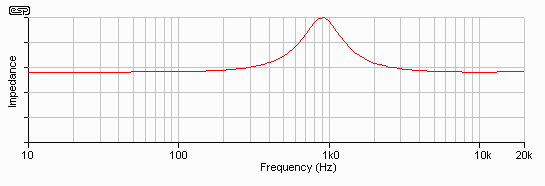
Figure 3.5 - Tweeter
Resonance
Experimentation is made easier with the following procedure. The first requirement is to plot the impedance of the tweeter or midrange driver, which should be done with reasonable accuracy. The resistance used in the network will be equal to the DC resistance of the voice coil - that much at least is quite straightforward. With the procedure explained below, I eventually arrived at the network shown in Figure 3.6 - this is hardly a trivial circuit to implement, especially with a relatively large capacitance. Again, the capacitor does not necessarily have to be "audiophile" quality, so a bipolar electrolytic could be used in this circuit as well - but the same caveats apply as with the woofer inductance compensation circuit. A bipolar electrolytic will change value over time, and the compensation circuit's performance will deteriorate as capacitance is reduced with age.
There is a strong case for manufacturers of midrange and tweeter drivers to offer a compensated version of their drivers, which would simplify the process considerably. At the very least, the needed parameters should be supplied to allow us to calculate the values needed. Regrettably, I have never seen the parameters or a suggested circuit with the specifications for any tweeter - IMHO this is the very least the manufacturers could do to help us all out on this. Instead, we are left to our own devices to determine the network by trial and error. I find this to be somewhat irritating.
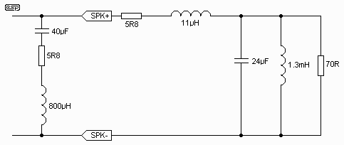
Figure 3.6 - Compensation
Circuit, and Equivalent Circuit of Tweeter
Unfortunately, it is extremely difficult to get the required details for most tweeters. The resonance is almost always quoted, but most of the time it is difficult to find the voice coil inductance, let alone the Qts and Vas, which would enable one to calculate the required network. The values I used in the simulations are assumed, and gave a resonance at about the right frequency - the reality will (of course) be different, and will differ even further from one tweeter to another. Some basic measurements on a selection of tweeters confirmed that the simulation is not too far off, although it may be a little broader than some tweeters.
The Q of the compensation circuit must be the same as the resonance Q, or it will simply form a sharp notch in the middle of the resonance peak (Q too high) or a broad notch that spans the resonance (Q too low). Unfortunately, this is not as easy as it may first appear, but it is not actually difficult once you know what to do.
As a first approximation, find the (actual) resonant frequency of the tweeter. You will need a small amplifier, and a resistance of about 10 ohms. Wire the 10 ohm resistor in series with the amplifier output and the tweeter. Keep the output voltage as low as possible (less than 1V RMS). Change the frequency of the audio oscillator slowly and note the frequency where the voltage directly across the tweeter terminals is at its maximum. Reduce the frequency slowly, until the level has decreased by 3dB (i.e. 0.707 of the previous level). From this, you can calculate the required capacitance that will null the inductive component of the resonant peak.
Measure the DC resistance of the voice coil, and note the resonant (Fo) and -3dB (F3) frequencies - you will need both for the next steps.
Capacitance is calculated from the formula ...
C = 1 / (2 *The details of the simulated tweeter are* Rvc * F3)
L = 1 / (4 *2 * Fo2 * C)
Rvc = 5.8 OhmsSubstituting our tweeter, we will obtain the following ...
Fo = 907 Hz
F3 = 635 Hz
C = 1 / (2 *These values will be difficult to obtain, and substituting 40uF and 800uH caused such a small error that it is of little consequence (it actually improved matters very slightly :-)* 5.8 * 635) = 43uF
L = 1 / (4 *2 * 9072 * 43-6) = 716 uH
Note that this procedure is intended as a starting point only, and you will almost certainly need to experiment if you want the flattest possible impedance. Small variations will not cause significant errors, so it is not beneficial to go to extremes.
Again, when you have completed the network, connect it (and the tweeter) to the test setup shown in Figure 1.1 and measure the response. It should be quite flat (within 1dB) across the resonance frequency.
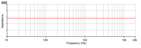
Figure 3.7 - Tweeter Impedance
With Correction Circuit
The impedance is now commendably flat, but at the expense of overall impedance, which is reduced from the nominal 8 ohms to the real impedance of the tweeter - in this case, about 6 ohms. This figure must be used when the crossover network is designed - not the nominal 8 ohms impedance. This is a very common mistake made by the novice, and from what I have seen, quite a few professionals as well. The nominal impedance is just that - nominal. When designing the crossover, the actual measured impedance must be used - always!
Figure 3.8 shows the result of the crossover with and without the correction network. This was simulated with a 12dB Bessel filter, and as you can see, there is a profound difference. This is the AC amplitude response only - the actual frequency response (dB SPL) will be quite different in most cases, but will reflect (to a modest degree) the problems that are immediately apparent from the diagrams.
An uncompensated (or partially compensated) tweeter can actually be used in a 12dB filter with little audible difference, provided there is sufficient "distance" between the crossover frequency and resonance. However if you are going to go to all that trouble to build the "ultimate" speaker system, you might as well go the extra mile (kilometre?) and get it right.

Figure 3.8 - 12dB Filter
Response With (a) and Without (b) Compensation
The effect is much worse with a 6dB filter, and this is shown in Figure 3.9. Note the tweeter resonance - it is completely undamped, and the attenuation of a 6dB filter is obviously not sufficient to reduce power to a respectably low level, even though the crossover frequency is set to 3kHz.

Figure 3.9 - 6dB Filter Response
With (a) and Without (b) Compensation
As you can see in (a), the tweeter signal is down by only about 10dB at resonance, and the uncompensated version is very much worse. Somewhat surprisingly (somewhat ??), the audible effect is not as bad as these diagrams indicate, but there is no doubt that for a high quality system, the effects are there to be heard - you just have to know what to listen for.
3.2 Amplifier
Impedance
If the speaker impedance has an effect on the crossover
performance, then it follows that the amplifier's output impedance will also
have an influence. With the majority of transistor amps, this is not an
issue, but a valve amp is very different indeed.
Most valve amps have an output impedance that is at least a few ohms, and for the sake of the exercise, we will assume an impedance of 4 ohms.
In a crossover that was previously completely flat when driven from a zero ohm source (a 12dB Bessel filter), there is a 1.5dB (approx.) peak at the crossover frequency when the source impedance is increased to 4 ohms. The effect is less pronounced than with a variation in loudspeaker impedance, but may be considered objectionable nonetheless.
Again, this is not allowed for in any speaker that I know of. If a speaker is to be able to be driven with either a valve or transistor amp, then a switch is needed to modify the crossover to suit the source impedance. Any claim as to "audiophile" performance is negated if the speaker cannot be accurately matched to the amplifier that will be driving it.
This also rather destroys the "audibility of cables" argument, since those
who can "clearly hear a difference" between two equivalent quality cables,
rarely seem to hear the peak in response that occurs when they use a valve vs.
transistor amplifier. One of these effects is far more pronounced than the
other - I shall leave it to the reader to decide which is likely to be more
audible ![]()
3.3
Temperature
In case you were wondering, the voice coil
temperature used in the examples below (150oC)
is not as outrageous as it may seem. Since loudspeakers have an efficiency
of typically 1% or less, this means that 99% of all the power going to the
speaker must be dissipated as heat. Although there is some air movement
through the voice coil gap, it cannot keep the temperature down low enough to
ensure that the effects described will not disturb the behaviour of the
crossover network. An efficiency of 1% indicates just over 92dB/m/W, which
is quite a respectable figure in the world of loudspeakers!
Copper has a thermal coefficient of resistance such that its resistance increases by 0.428% per degree Celsius. We can safely assume that the impedance is based on "room temperature", which will generally be in the order of 20oC. When power (in the form of music or test signals) is applied to a speaker, the voice coil temperature must rise. Given a typical 6.6 ohm (DC) voice coil for an 8 ohm nominal speaker, at 150oC, the resistive component alone will rise to about 11 ohms - and naturally the impedance must be somewhat greater than this figure.
The loading on the crossover network is then radically different from the basic design figure of 8 ohms, or any corrected impedance obtained by using a zobel network. The real issue here is that there is virtually nothing you can do about it, so the loading on the crossover network will vary depending on how loud the speakers are playing!
You may have read reviews where a loudspeaker system was described as becoming "edgy" or "brittle" at higher levels. This may be because the amplifier was clipping, but it could also be the result of what is called "power compression". Woofers are particularly susceptible to this phenomenon, since they are expected to handle more power than tweeters. Many tweeters use ferro-fluid in the voice coil gap, which not only improves damping and reduces resonances, but also gives a higher power handling. This means that the voice coil temperature rise will often be much lower than for the woofer, so the relative efficiency (in dB/m/W) from the tweeters remains the same, and that of the woofer falls (as it must if the impedance increases).
Of course, some speakers may have been optimised for a higher than average listening level, and these are likely to sound somewhat dull at "normal" listening levels.
That the impedance varies with power level is not conjecture, it is a fact, and the effects can be proven in demonstrations and by measurement - this variation is as dictated by the laws of physics, and no speaker manufacturer has been able to break those laws.
The question remains - what can be done about it?It would be possible to use a thermistor (a special resistor whose resistance varies with temperature), but matching its thermal characteristics to the voice coil would be a formidable task. Since a thermistor is by definition a non-linear device, it may also introduce distortion of its own - a less than desirable outcome.
The answer (regrettably) remains - virtually nothing!
It is not only the power compression of relative levels that has an effect in this case - the crossover frequency will shift with volume! It really has no choice, since the voice coil will change impedance, and the crossover frequency (and filter damping) is determined by the load - the loudspeaker, and any additional network you use to equalise its response.
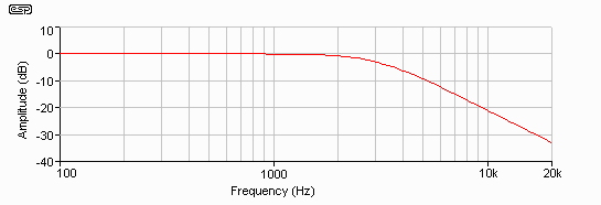
Figure 3.10 - Filter Performance
at Ambient Temperature (Z = 8 Ohms)
As an example, let's assume that a loudspeaker has a flat impedance curve, and is exactly 8 ohms. A Butterworth crossover may be designed that will have a -3dB frequency of 3kHz (Figure 3.8). Should the impedance rise to 11 ohms (as in the above example of a 150oC voice coil temperature), the -3dB frequency will increase to over 3.8Hz, and the filter shape is changed. A Bessel filter will become Butterworth, or a Butterworth filter will now be Chebychev! This is shown in Figure 3.11, and the typical peak before rolloff of a Chebychev filter response is easily seen - as is the frequency shift.
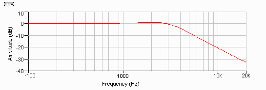
Figure 3.11 - Filter Performance
at Elevated Temperature (Z = 11 Ohms)
Meanwhile, because of the relatively low power in the tweeter, and possibly due to the effects of ferro-fluid, its temperature rise may have caused the impedance to rise to only 9 ohms (example only). Even this is sufficient to cause the crossover frequency to fall to about 2.7kHz, and will also change the filter shape (but to a lesser degree).
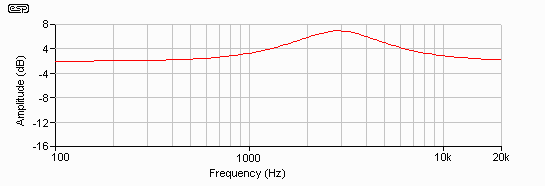
Figure 3.12 - Combined Crossover
Response at Elevated Temperature
A crossover that at ambient temperatures had a nice stable (and well defined) crossover frequency of 3kHz, now has a 1.1kHz overlap! The audible effect is a disaster, since there will be quite a prominent peak (almost 5dB) at around 2.8kHz - the approximate centre frequency of the overlap region. Needless to say, if the tweeter had an equivalent temperature rise (due to the use of an aluminium voice coil, for example), then the overlap region becomes greater, and the peak is worsened - the amplitude will be relatively unaffected, but the peak will be wider as the two speakers are reproducing the same frequencies. The effects on relative phase and dispersion are less predictable, but we can safely assume that the outcome will be undesirable! (To put it mildly.)
A further consideration (although probably of minor consequence except in extreme circumstances) is that the tweeter will now absorb a little more power, causing its voice coil temperature to rise further, thus lowering the crossover frequency and allowing more power, thus raising the temperature even further (etc.). Whether this would reach destructive levels is doubtful - but the possibility exists! An amplifier pushed into distortion for extended periods could conceivably lead to this self destructive behaviour (assuming that the tweeter survives the high average power to start with).
This behaviour could be made to disappear completely when an electronic crossover is used. Although the details are not relevant to this article, a signal processor can be adapted to adjust the level to compensate for power compression in the drivers. To my knowledge this has never been done. The truth is, this is far less of an issue when an electronic crossover is used - the power compression still occurs, but there is no shift of the crossover slopes, so the effect is only on relative levels, and not the designed crossover frequencies. It is a simple matter to adjust the relative outputs of the electronic crossover to match the average power that will be used, so one could have a switch, marked "Soft", "Normal" and "Loud" if desired :-)
3.4
Atmospheric Changes
The loading on a loudspeaker cone, and
therefore its Theile/ Small parameters, will also vary with changes in the
atmospheric conditions. High humidity, altitude or temperature make air
less dense - such variations will cause changes to the loading on the cone, and
thus the speaker's parameters.
In reality, these are relatively small, except at extremes. Even at the extremes, the physiological effect on the listener will probably be far greater than the atmospheric effects on the loudspeaker, but I know of no tests that have been performed to measure the changes experienced by any driver with differing atmospheric conditions.
I doubt that there are vast differences, but it is an additional consideration worthy of further investigation - preferably by someone with access to an environmental test chamber. Relying on the vagaries of the weather and quickly taking some measurements is unlikely to yield meaningful results.
Fortunately, it is unlikely that the performance of a passive crossover will be affected to any audible degree by normal variations in atmospheric conditions.
Having digested the above, you now bravely decide to go ahead regardless. The next task is to select the filter slope and alignment. Again, there are compromises that must be made, and it is important to select the most appropriate crossover to suit the drivers you are using.
4.1
Slope
Selecting the best slope is important, both to protect the
tweeter (in particular), and to ensure that the drivers are all operated within
their optimum frequency and power handling ranges. A first order
(6dB/octave) filter has the most predictable response, and is affected less by
impedance variations than higher orders. On the negative side, the
loudspeaker drivers will be producing sound at frequencies that are very likely
outside their upper or lower limits. At low powers (less than 10W or so),
this is usually not a major issue, but it becomes much more important when
amplifier powers of 50W or more are considered.
Second order filters (12dB/octave) are better at keeping unwanted frequencies out of the individual speakers, but are more complex, and are affected by impedance variations to a much greater degree. The tolerance of the components used will also have a greater effect, so it is not uncommon for designers to make the inductors specifically for the job, rather than attempting to use "off the shelf" coils. The capacitance used must also remain predictable and constant over time and power, which specifically excludes the use of bipolar electrolytics (well apart from any other failings they may have - either real or imagined).
The design task becomes more complex and the tolerances more exacting as the order is increased. A third order (18dB/octave) filter requires closer tolerances than a second order, and is again even more susceptible to any impedance variations than the 12dB filter. Fourth order (24dB/octave) increases the complexity and tolerance requirements even further - a point must be reached where the requirements versus the complexity and sensitivity will balance out. With passive crossovers, I now believe that anything over 12dB is a waste of time, especially when the effects of voice coil temperature are considered.
Even with the second order filter, the possible variations (especially those caused by voice coil temperature) can totally ruin the sound - regardless of the quality of the components or care in making the crossover. I shall leave it to the reader to determine for him/her self where to draw the line.
4.2 Filter
Alignment
The traditional passive crossover is (and for the most
part always has been) the Butterworth - at least for second order filters and
above. Although this may seem the ideal, it is not, since there is a 3dB
peak at the crossover frequency when the outputs are summed. It is now
commonly accepted that this peak is also present in almost all speaker systems
when the loudspeaker outputs are summed acoustically - i.e. in normal operation.
Again, this is a world of compromise. My preference is for a Bessel alignment, since it provides a close approximation to a Linkwitz-Riley alignment, and has zero peak or dip at the crossover frequency. Since the Q is lower, it is also marginally less sensitive to variations in loudspeaker driver impedance, but this is not something that should be relied upon.
As I mentioned above, a first order filter has a Q of 0.5 as a matter of course, and this cannot be changed. This produces a Bessel filter by default, and because the rolloff slope is so gradual, a Linkwitz-Riley alignment is not needed for an overall flat response.
Second order filters have an overall phase reversal, and this must be accounted for. In a two-way system, the tweeter is usually connected out of phase - the negative terminal is connected to the "positive" or hot output of the filter network. In the case of a three way system, the midrange driver is most commonly reversed in phase, with the woofer and tweeter connected normally. This maintains the overall phase integrity of the crossover for all drivers. A deep notch is created at the crossover frequency if the phase reversal(s) is/are not done properly - this is objectionably audible!
The formulae for calculating the various filter component values are not at all complex, although they may appear so at first glance. There are quite a few variations, depending mainly on the slope and alignment. I have included those for 6dB and 12dB variations only, as I don't feel that there is anything useful to be gained by using higher order passive filters - especially in light of the discussions above.
Since it has been shown that the speaker impedance will rarely be 8 ohms - particularly when impedance correction has been applied - I will use 6 ohms for all calculations to follow. You will need to determine the exact impedance of your impedance corrected drivers yourself. It is unlikely that they will exactly correspond to my examples, but you might be lucky :-)
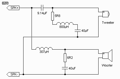
Figure 5.1 - 6dB/Octave 2-Way
Passive Crossover
The first filter must be a 6dB two way crossover. This is about as simple as a circuit can get (except that it is actually quite complex when all the parameters are considered). Impedance correction components have been included for reference. I designed this filter using the same drivers used as examples above, and the crossover frequency is 3,000Hz.
C = 1 / ( 2Where:Z f )
L = Z / (2f )
C = capacitance in faradsThese can be "simplified", and reduce to the following ...
L = inductance of the coil in Henrys
f = frequency in hertz
Z = (actual) impedance of the speaker in ohms
C = 0.159 / ( Z f )Thus, for a crossover frequency of 3,000Hz at 6 ohms (a standard I shall use throughout these examples) ...
L = ( 0.159 Z ) / f
C = 0.159 / ( 6 * 3,000 ) = 8.83 uFThe crossover frequency is the -3B point on the response curve, but since this is a Bessel filter, the response is completely flat across the crossover point.
L = ( 0.159 * 6 ) / 3,000 = 318 uH
A schematic for a 12dB crossover using the simulated drivers as used above is shown in Figure 5.2, and again includes the impedance correction circuits. The schematic for nearly all conventional parallel crossovers is the same, only the component values change. Note that the component values have been calculated for the simulated drivers, and should not be used as shown - this also applies to Figure 5.1.
Note especially that the tweeter is wired with its phase reversed - this is important, and must not be forgotten. This only applies to the 12dB example.
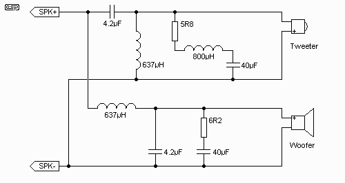
Figure 5.2 - 12dB/Octave 2-Way
Passive Crossover
The same circuit is used for all calculations for 12dB filters. Using a 12dB Bessel filter network (which gives a Linkwitz-Riley alignment) the following (simplified) formulae will determine the component values ...
C = 0.0796 / ( Z * f )The derivation of these is marginally interesting, and will help you to understand the Butterworth and Bessel alignments a little better. The full original formulae are ...
L = ( 0.3183 * Z ) / f
C = 1 / ( 2 *Where* Z * d * f )
L = ( Z * d ) / ( 2 ** f )
d = 1/ Q = 1 / 0.707 = 1.414 (Butterworth) or ...A Bessel filter (for our purposes) has a Q of 0.5 or a damping of 2. Note that this has nothing to do with amplifier "damping factor" which is completely different, and as long as it exceeds about 10, has no influence on crossover performance (although woofer performance may require the amplifier damping factor to be higher than this).
d = 1 / Q = 1 / 0.5 = 2 (Bessel)
| Updated 05 Nov 2001 - a reader pointed out that I had made an error in the woofer sensitivity calculation, so this section has been revised - with the correct information this time. My apologies for any inconvenience. |
It is rare that the woofer and tweeter (or midrange driver) will have the same sensitivity (i.e. efficiency). The woofer should have the lowest efficiency, since it will require the most power, and any network that reduces the level to the woofer will absorb a disproportionately high power, and will adversely affect the damping factor.
The driver selection is very important - ideally, all drivers will have the same efficiency, and no attenuation will be needed. In the real world, this will rarely be the case. Attenuator networks are a necessary evil - it is immeasurably better not to use them at all, but they cannot be avoided unless the drivers have exactly the same sensitivity.
For the purpose of the exercise, assume that the tweeter has an efficiency 2.8 dB greater than the woofer/midrange. This means that the level must be reduced by 2.8dB, or the speaker system will sound too bright. Remember that this network can alter the impedance presented to the crossover network, so you either must design for the impedance with the attenuator in circuit, or ensure that the attenuator presents exactly the same impedance as the speaker.
The very first exercise is to determine the resistive drop caused by the pow pass inductor (this step is almost always forgotten!). A typical coil of this value, using 0.8mm wire, will have a resistance (Rl) of about 0.53 Ohm. We can calculate the low frequency loss in dB with the formula ...
dB = 20 log ((Rl / Z) + 1)For our example, this gives ...
dB = 20 log ((0.53 / 6) +1) = 20 log (1.088) = 0.73 dBWe have now found that the woofer's sensitivity is slightly lower than before, so we need an attenuation of 2.8+0.73=3.53dB, which we can safely round down to 3.5dB. The tweeter must therefore be reduced in level by 3.5dB so that it matches the sensitivity of the woofer.
The attenuator must be placed either before the filter (basically not a good idea), or between the crossover filter and the driver - including any impedance compensation. The driver and its associated impedance correction network should be considered as one, and they should not be separated (unless you feel like re-calculating the entire crossover and compensation networks). I have seen a number of design examples that state that the attenuator should be before the crossover - wrong, wrong, wrong!
This practice increases power dissipation needlessly, since the attenuator must work over the entire frequency range. If attenuation is after the crossover, then power requirements are greatly reduced.
The simplest attenuator is a series resistor, but this changes the load presented to the crossover network. Unless the network is designed for the impedance presented by the combination of driver and attenuator resistor, this is unacceptable. As a result, the most common attenuator is an "L" pad. This is shown in Figure 6.1, and maintains an impedance of 6 ohms to the crossover, but reduces the tweeter level by 2dB.
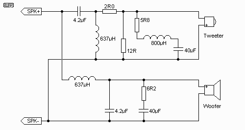
Figure 6.1 - 2dB L-Pad
Attenuator
The calculations are quite irksome, and (as always) can be tiresome. The problem is that the resistances are interdependent - if one changes, then so does the other. The idea is to maintain the same impedance we had before, or re-calculate the crossover network. The latter is very much easier, but means that the high and low pass sections will no longer have the same component values. For the purposes of the exercise, I will maintain the crossover, and make the resistors provide the same 6 ohm load as before.
Essentially, there are two ways to calculate an L-Pad - the simple way and the hard way. I am going to use the hard way, because it is simpler! How can this be? If I give you a formula that just spits out the value, that is easy, but you will never remember the formula. On the other hand, if I show you how to derive the formula using simple ohm's law, then you will be able to use the basic method, and you will have a much better chance of remembering it.
As suggested, the tweeter in this example is 3.5dB more efficient than the woofer + inductor combination, so must be attenuated by this amount. Please remember that these are examples only, and your situation will probably be completely different. First, we need to convert 3.5dB into a voltage ratio (Vr) ...
dB = 20 log (V1/V2) = 20 log (Vr), so reversing the formula we get ...For this example, we have 3.5dB, so substituting ...
Vr = 1 / (antilog (dB / 20))
Vr = 1 / (antilog (3.5 / 20)) = 1 (antilog 0.175) = 1 / 1.496) = 0.668The voltage presented to the tweeter will therefore be 0.668 of the input voltage. Since we want to preserve the impedance presented to the crossover network (rather than redesign the rotten thing :-) this makes the calculations a little harder.
As I said above, it is not impossible to derive a formula for the pad, but it is more convenient to work it out the long way - largely because this provides a better understanding of the process. We will assume an input of one volt - simply because it is convenient to do so.
Firstly, we need to determine the current that will flow into the load (Z) ...
I = V / Z = 1 / ZNow, find the voltage drop across the series resistor Rs, then the value of Rs ...
Vs = 1 - VrThe process is quite simple so far. Now we need to determine the value of the parallel resistor, Rp. We already know that the voltage across the parallel combination of Z and Rp - it is equal to Vr (I told you that an input voltage of 1V was convenient, didn't I? :-) The value of I (current) does not change, so we can determine the current through Z and Rp easily, and then Rp itself ...
Rs = Vs / I
Iz = Vr / ZNow, let's substitute all the values for the example into the formulae. As I said, this is a little tedious, but easily remembered. Recall does not come from rote learning, it comes from understanding, and this is just simple arithmetic and Ohm's law.
Ip = I - Iz
Rp = Vr / Ip
I = 1 / Z = 1 / 6 = 0.1667 AmpsThat was easy enough, so now for Rp ...
Vs = 1 - Vr = 1 - 0.668 = 0.332 Volts
Rs = Vs / I = 0.332 / 0.1667 = 1.99 (2.0) Ohms
Iz = Vr / Z = 0.668 / 6 = 0.111 AmpsNow we might want to check that the values really will give us what we wanted - I recommend this final check, because there are resistor values that are easily created (or are standard), and we want to use these if possible. As a result, we will substitute 2R (2 x 1R in series) for Rs, and 12R for Rp, as these are standard values. The first thing we need, is to determine Rt - the total parallel combination of Z and Rp (Z || Rp). We could do that from the current calculated earlier, but that may re-introduce any error made earlier.
Ip = I - Iz = 0.1667 - 0.111 = 0.0557 Amps
Rp = Vr / Ip = 0.668 / 0.0557 = 11.99 (12.0) Ohms
Rt = 1 / (1 / Rp + 1 / Z) = 1 / (1 / 12 + 1 / 6) = 1 / (0.0833 + 0.1667) = 4 OhmsDamn! That was close
Vd = (Rs / Rp) + 1 = (2 / 4) + 1 = 1.5
dB = 20 log(Vd) = 20 log (1.5) = 3.52 dB
An error of less that 0.1dB is completely insignificant, and can be ignored completely, but in this case, we got almost exactly the attenuation we determined right at the beginning. In case you were wondering, this was not deliberate - it just turned out that way. If you are careful with your calculations, it will always turn out this way.
The resistors should be wirewound power types, and the actual power is determined by the input power from the amplifier.
There will always be power losses in a passive system - this is generally referred to as "insertion loss", and all resistors and inductors will create power loss and thus, heat. Capacitors will generally contribute very little loss, and will not get hot - a potentially notable exception being bipolar electrolytics. This is another very good reason not to use them, but the main reason is that their value will change over time, and will upset the crossover frequency.
The power loss is naturally proportional to the input power, and for our example, I shall assume a maximum amplifier power of 100W. Use the chart below to determine how much power will go to the tweeter, using a crossover frequency of 3.0kHz.
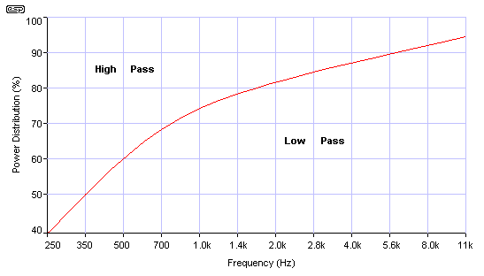
Figure 7.1 - Power Distribution
Chart
Working along the frequency axis, we see that at 3kHz, the power in the low pass section will be about 85% of the maximum (85W), so the high pass power level is about 15%, or 15W for our 100W system. We are now in a position to work out some power ratings for the resistors, and can also calculate the inductor losses. Not that we can do anything about losses in inductors, but we can at least decide whether they need to be mounted on fire proof material (just kidding).
We already know that the woofer's zobel network only needs to operate at over 650Hz, so using the chart again, we see that the low pass section will get about 65% (65W) at that frequency. The zobel network is a high pass section (yes it is!), so the maximum power will be at above 650Hz, where high frequency energy is less than 35W. Since the power progressively reduces, the resistor will never have to deal with more than about 20W peak. Since no-one (well, no-one who is going to go to all this trouble to make an almost perfect crossover) will listen at 100W continuous, we can safely assume an average power of about 10W - this corresponds to the "typical" peak to average ratio for music of 10dB.
Woofer zobel resistor ...
I would suggest a power rating of 10W
for the zobel resistor - this provides a very large safety margin.
Tweeter resonance compensation ...
The tweeter power at resonance
is more than 20dB down from the maximum level using a 12dB crossover.
Since this is the case, a 5W resistor is more than adequate.
Tweeter L-Pad ...
The L-Pad will be subjected to a maximum of 15%
of the power, but will dissipate very little of this. 5W resistors are
again more than enough to handle the power.
Woofer inductor ...
Since we determined that the resistance will
be about 0.53 ohms, so at full power it will dissipate less than 10% of the 100W
input, which is about 10W. (0.53 ohms is 8.8% of 6 ohms) The average will
be much less than this, and heating will not be a major problem.
Note that all the losses above are wasted power, so in all, only about 90W of the amplifier power will ever get to the speakers themselves, and about 10% will simply be wasted as heat - inside the cabinet! This will eventually cause the air inside the box to heat up enough to change the characteristics of the enclosure - especially sealed boxes. This is added to the heat generated in the loudspeaker voice coil, a good proportion of which will remain in the cabinet, having no means of escape.
Perhaps you would be better off either mounting the crossover network on a heatsink on the outside of the box, or install it in a false (ventilated) base. And yes, I am serious. Apart from the heat (which is actually relatively low compared to that generated in the voice coil), the high sound pressure will cause vibration of the components. While I think that this is unlikely to be audible if everything is well fastened, there are claims from some quarters that microphony at this level is definitely audible. For the small additional effort, external mounting is recommended. It also make minor tweaks and adjustments much easier, since you don't have to remove speakers to get at the crossover.
Using the drivers simulated in this article, and using all the networks that were devised along the way, we have examined the complete 12dB/octave crossover network implementation. The tweeter is 2.8dB more efficient than the woofer (not allowing for the additional inductor loss), and is padded back with an L-Pad that reduces the signal while maintaining the impedance.
Use the examples above to work through your own crossover design - the final result is quite complex, and will not be inexpensive to build. This is the price to pay when the best possible performance is to be obtained from a passive crossover (now, wouldn't it have been easier to tri-amp the system instead?).
All that remains is to explain how to wind the coils you will need. It may be possible to obtain them commercially, but I doubt it, since the values are unlikely to match those you will find at most electronics outlets. You may be able to get coils that are slightly above the values you need, and remove a few turns until you get it right
An inductance meter is essential for any of this - many are available in (even relatively cheap) digital multimeters, and these should be sufficiently accurate. It will be virtually impossible to get the coils right without a meter - you can measure their resonant frequency with a known capacitance and calculate inductance from that, but it is very tedious!
If you want to wind your own coils, I suggest you use either of the following the online calculators, available at ...
Shavano Online Music - Inductance CalculatorBoth of these are very much easier than using the formula below. You will still need to measure the final result to make sure that it is within a reasonable tolerance. Much as it might appeal, don't use iron or ferrite cored inductors for crossovers. There are advantages in that they are smaller and have less power loss, but the distortion and risk of saturation (at which point inductance drops dramatically) are not worth it (IMHO).
Barry's Inductor Simulator
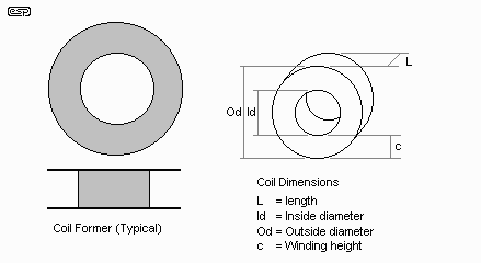
Figure 8.1 - Typical Coil Former
and Dimensions
From the above, the necessary dimensions used in the formulae can be easily determined. These apply to the winding itself, not the former (which may be a temporary affair, as it is only needed while winding the coil). There are actually several different formulae that may be used - all are empirical, and require some experimentation to arrive at the correct value (or the correct number of turns for a given inductance and wire size).
Some I found are not worth the paper they are written on - they either don't work, or work only under certain limited circumstances. The formula below is due to Wheeler ("Simple inductance formula for radio coils" 1928), and is still probably the most accurate so far (which is scary - a formula 73 years old has never been surpassed). The original (using inches (mutter, mutter)) is ...
L = 0.8 * a2 * N2 / (6a + 9l + 10c) uHWhere
N is the number of turns.All dimensions are in inches. This is easily converted in a spreadsheet or program, but modifying the formula itself is too tedious. For a real example of a coil wound with 0.83 mm (20 AWG) wire, having a design inductance of 637 uH and a resistance of 0.53 ohms has the following dimensions ...
a is the average radius.
c is the height of the windings
l is the length of the coil.
N = 99 turnsThese figures were arrived at from one of the Shavano online simulators, and when the data is plugged into the very basic spreadsheet I have done so far indicates that this coil will have an inductance of 635.17 uH. This is a very small error, and will be of no consequence in practice. According to the simulator, power handling is 180 Watts, and it will require approximately 15.9 metres (52.3 feet) of coil winding wire.
l = 11.2 mm (0.44")
Id = 44.8 mm (1.76")
Od = 58 mm (2.28")
c = 6.64 mm (0.26")
Never use plastic coated wire for winding inductors - enamelled winding wire is essential. I am contemplating writing a coil winding calculator - if I get enough interest I shall do so, but as suggested before, it is probably simpler to buy ready made coils (of higher inductance than required) and remove turns to get the exact value you need.
When the inductance is correct, dip the coil into varnish (most clear floor varnishes are quite acceptable), and let it dry thoroughly before use. This ensures that the turns cannot move - we don't want to add vibration sensitive coils to the already suspect passive crossover. It will also prevent rattles - of the type that will drive you nuts, because you will have no idea where (or what) is rattling!
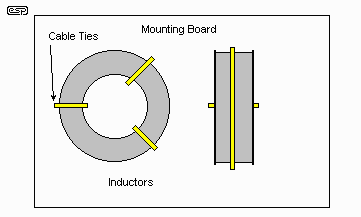
Figure 8.2 - Mounting Inductors
to Minimise Coupling
When mounting the coils, keep them well separated, firmly attached to the mounting board, and ensure that there is minimal mutual coupling by placing the axes at right angles to each other as shown in Figure 8.2 - transformers in the crossover you don't need. Use cable ties and silicone, hot-melt or epoxy glue to make sure the inductors are firmly fastened to the mounting board and cannot move. Any movement will eventually fracture the copper wire if it is rigidly attached, so a loop of wire from the coil (or stranded wire leadouts) will ensure that you don't have electrical failures.
This article has covered the topic in far more detail than you will find in most references, and explains some of the things that most articles don't even touch upon. One thing that should be quite clear by now, is that a full 3-way passive crossover, with everything done properly will be very expensive to build. It is also time consuming, and the final result will only ever be as good as the effort you are willing to put into getting everything right.
A few generalised recommendations are in order ...
A Quick
Rant
The "simple" passive crossover is actually vastly
more complex than is commonly believed. The "new" DiauralTM "inductor only" crossovers are not a
panacea for the ills of the world (despite massive marketing hype to the
contrary), but fall into the "simple and grossly coloured" category. There
is nothing (repeat - nothing!) about the Diaural system that is new, or will
benefit the vast majority of systems. They will probably sound "lively"
and perhaps "musical" by initial direct comparison to a conventional crossover,
but require very careful driver selection indeed if gross response and phase
errors are to be avoided. These are even patented - how in God's name
those ratbags got a patent on something that has been done by others for years,
we will never know. I have a copy of the patent, and all the variations
are shown - so much for the "cone of silence" that was placed on anyone who saw
them in the early days. There is absolutely nothing remarkable about the
principle, other than the complete and total neglect of almost everything I
covered in this article.
So there we have it. I doubt that this is the "last word" on passive crossovers, and I'm equally sure I have left out something that should have been included. I don't profess to be an expert on the design of passives, but my design background and experience (as well as that of a few others) has helped in the analysis of the loudspeaker driver behaviour, in the electrical sense at least.
The mechanical behaviour is something else again, and many excellent papers have been written on the subject. In particular, I suggest Lynn Olson's series of articles (of which I was made aware just as I had almost completed this paper).
Lynn Olson ...The material presented is mainly to do with cone break-up effects, but some mention is given to impedance correction as well. There are obviously many others, and an enormous amount of research has been done by a vast number of people, all striving for the same thing - the perfect loudspeaker. We don't have it, and may never get it - but when (or if) we do, there will always be someone who says it stinks. Such is Hi-Fi.Looking Over My Shoulder, Parts I and II The Soul of Sound